Electric CAD program on Linux

If you are an electrical engineer, or someone who likes to dabble in designing electrical circuit boards (or anything with regards to electricity) and you're looking for a FOSS (Free, Open Source Software) CAD program to aid you in the process, then Electric might be the solution. Although it doesn't have the most modern looking GUI - what electrical engineer really cares about how "modern looking" a GUI is? - Electric offers a lot of features and will serve you well in your designs.
Let's take a look at the features Electric offers as well as the installation and basic usage of the tool.
Features
- Design rule checking
- Electrical rule checking
- Simulation and simulation interface (many options)
- Generation (ROMs, PLAs, Pad Frames, etc.)
- Compaction
- Routing
- VHDL compilation
- Silicon compilation
- Network consistency checking (LVS)
- Logical Effort analysis
- Project Management
Not a bad feature-set for a piece of free CAD software.
Design types
- MOS (many CMOS and nMOS variations)
- Bipolar and BiCMOS
- Schematics and printed circuits
- Digital filters, Temporal logic
- Artwork
Supported file formats
- CIF I/O
- GDS I/O
- EDIF I/O
- DXF I/O
- SUE Input
- VHDL I/O
- Verilog Output
- EAGLE, PADS, and ECAD Output
- PostScript, HPGL, and PNG output
Available platforms
- UNIX
- Macintosh
- Windows
Installation
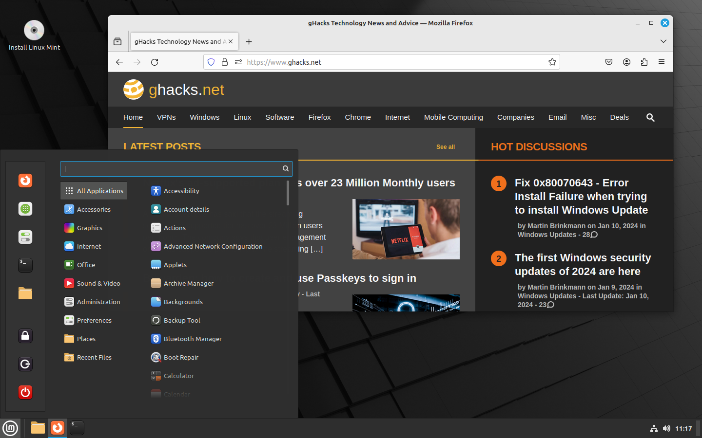
I will demonstrate the installation on the Ubuntu distribution. This is quite simple, just follow these steps:
- Open up the Ubuntu Software Center.
- Search for "electric" (no quotes).
- Click the Install button.
- Type your sudo password and hit Enter.
- Let the installation finish.
Upon completing the installation you will find a new sub-menu in your Applications menu - Education. In this menu you can click the Electric entry to start the program.
Usage
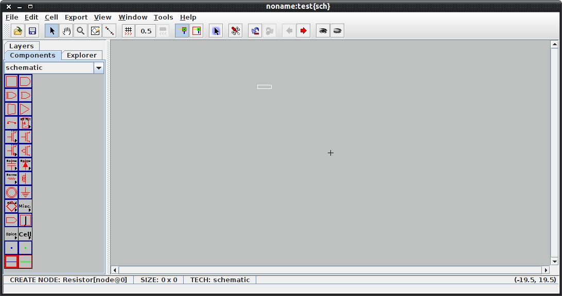
Obviously you need to be familiar with the science and art of electrical engineering to make full use of this application. But even a newbie can tell this tool has a lot to offer. Figure 1 shows the basic Electric window. The largest pane is your working pane and displays your drawing one cell at a time. To move cells you click the right or left pointing arrows in the tool bar (hover your mouse and you will which ones thanks to a tool tip).
The left pane you have the elements necessary to create your drawings. To add an element you double-click and drag it to the the working pane.
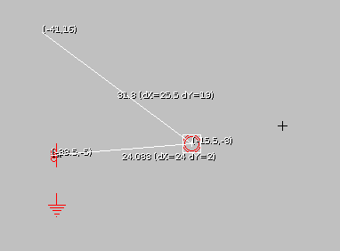
One very nice feature (that is not highlighted) is the ability to measure from element to element within a cell. To do this place your elements in the cell and then click on the Toggle Measuring Distance button. When you do this your cursor will change and you can then click on one object and drag your mouse to the next to see a very precise measurement for that distance.
From the list of elements you will find most of the standards such as: Transistors, resistors, grounds, power, Capacitor, Global-Signal, Inductor, And, Or, Buffer, and much more.
Final thoughts
I believe Electric will satisfy any electrical engineer looking for a free, open source solution for their electrical schematic needs.
Advertisement


I think you have misunderstood this one. “Electric” is a VLSI (Very Large Scale Integration) Design System, and has nothing to do with component level electronic or electrical design or PCB layout.